Project sector: Operation and Maintenance (O&M)
Project status: Completed
Project location: Lar Dam, Tehran City, Tehran, and Mazandaran Provinces
Project objective:
- Finding the unknown leakage points in the body and reservoir of the dam
- Finding remediation measures for solving the problems
Project starting date: November 2016
Project completion date: November 2017
Project duration: One year
Abstract
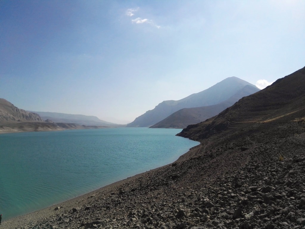
Lar Dam, situated in the northeast of Tehran with access to Haraz road (Tehran- Caspian Sea road) and 75 Km distance from Tehran is the main drinking water source of the capital city of Tehran which has the largest water reservoir around Tehran. The main purpose of the construction of the Lar dam is to supply the drinking water of the metropolitan city of Tehran as well as the irrigation of agricultural lands of the northern province of Iran.
The study area is a tectonically active area and the bed and walls of the reservoir include seven geological structures among which Lar limestone is the most challenging one due to the high rate of dissolution.
The current karstic structure of the Lar and Tiz-Kuh has extended to deep levels. Its ultimate depth has still remained unknown. This issue was observed in the first case of injection cement to fill karstic caves in the early years of the impoundment of the reservoir. Significantly, even in one case, 100000 tons of cement were injected to fill the holes, which had no effect on the impoundment of the reservoir.
Saman Ab Sarzamin Consulting Engineering Company (S.A.S) took several measures for investigating and study on this area, including:
- Reanalysis the results and outputs of reservoir researches
According to inspections and dying tests, most of the injected substances had existed through the Galugah and Haraz Springs and this fact indicates the relation between the mentioned springs and the reservoir. Moreover, it has shown that a few injections did not exist and remained in the reservoir or the exact location of their outflow was unknown. The primary focus of this study was on the available geological reports and reanalyzing the data that were obtained by Terra Company to identify potential leakage of the area. During the studies of S.A.S, in addition of the Tiz-Kuh structure, two new regions were introduced as suspicious points that needed more investigation, including (1) Right bank of the entrance to Emamanak Valley (SLP02 area), and (2) 1.5 Km upstream of Emamanak Valley (SLP01 area).
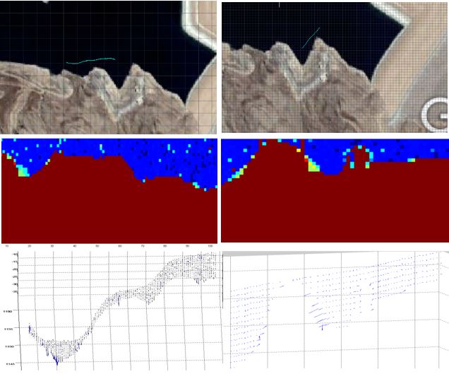
S.A.S. analyzed the outputs of Terra Company’s studies. The data were analyzed and converted into the visual output for better understanding of the status of the reservoir. This issue was conducted by codifying and programming in MATLAB Software, drawing a 2D diagram of velocity magnitude and the diagrams of flow vectors. One of the analyses of the changes in velocity is presented in a diagram. The weak point of these measures is related to the bad timing for surveying and surveying. At the end of September and early October, the water level was at 2474 m. Since many outlet points were identified above this level, it was preferable to measure the velocity at the time of the maximum level of the reservoir and more accurate information from outlet points could have obtained.
Identified probable leakage points for field monitoring
During this period, the water level raised from 2488.7 m to 2490.9 m. In addition, the Tizkuh structure and the body of the dam at the place of sinkholes were monitored in the second site visit, new cases were observed.
The first case was hearing the loud sound of streamflow from the inside of the rock in the Tiz-Kuh structure (P1 point). Injections at this point indicated definitive water leakage in the whole range of this level and the location of injection and exiting injected substance for future monitoring was determined. The large karstic holes and cracks that have not been identified in previous monitoring (like C1), were investigated with more details.
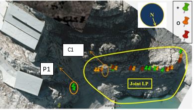
On 2017-Aug-05, a huge hole was observed at Joint LP, but due to the high water level, it was not possible to go inside it. In-field monitoring on 2017-Aug-17 by decreasing water level, it became possible to inspect the size of the cave, which called C1. Numerous corrosions and cracks on the wall showed the water leakage in C1. Injections showed the water leakage from the western cracks and holes in the cave and the body of the dam.
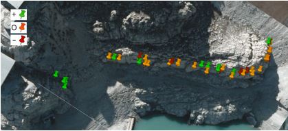 The results of investigations and dye test in field visit in July
In the right abutment and the structure of Tiz-Kuh besides dye injection in cracks, investigations were carried out with more details on the dissolution cavities. Above the level of LP04, a new crack observed. The scouring erosion in eastward and inside of the caves, the existence of wood and debris within a few meters inside of the cave were evidence of water leakage. A series of injections were carried out from 2491 m level to the lowest level 2482 m.
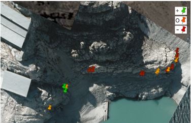 The results of field monitoring and dye injection in September 2017
Due to the decreasing of water level and appearing suspicious water leakage points, besides common inspections, detected leakage points in previous field visits were investigated again to measure the size and dimensions of the holes accurately. In general, three types of signs for water leakage were evident at these points, (1) one was changes in the color of the rock masses and darken them, (2) existence of dried algae and accumulation of them in holes and crack, and (3) decreasing the sharpening of the edges of rock masses which were the exposure of outflows.
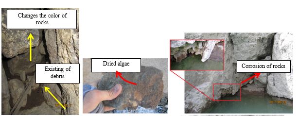 Evidence of water leakage
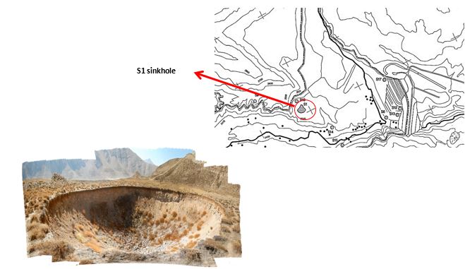
During a field visit on 12 October, a dye test was performed at suspicious areas. Also sampling from the surface of the rock with corrosion problem were conducted to make an assessment of the efficiency of past operations. Some sinkholes were visited such as the S1 sinkhole during this series of site inspection
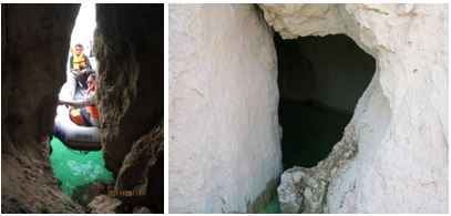
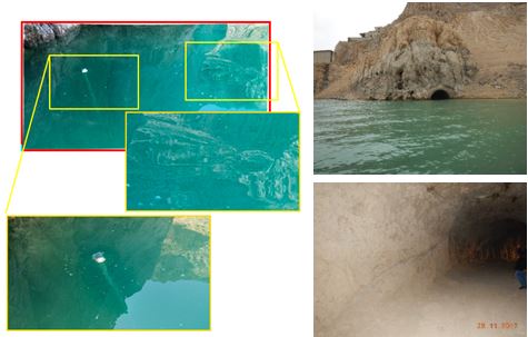
On the 28th of November, the last field visit was conducted to investigate the suspicious leakage points which had not been visited before. The diversion Tunnel 01 is one of the major leakage points. At high water levels, when the tunnel was 3 meters below the water surface, vertices were formed which indicated suction of water into the tunnel and depth of the lake. During several visits, by entering into the inside of the tunnel and observing cracks on the walls of the tunnel and debris inside the holes clearly revealed that water leakage from the body of the tunnel has happened. Since the tunnel was drilled by the explosion, the crack and holes became wider and the corrosion of stones has increased during these years.
 Vertices formed on above the Tunnel 01, visiting inside of the tunnel
Project outcome:
The diversion tunnel 01 as the main leakage point was monitored several times by S.A.S. The results of site visits indicated that the presence of numerous cracks on the walls of the tunnel and using explosion procedures to create this tunnel led to widening and increasing these holes and water leakage at this tunnel. The presence of caverns and boreholes on the way of this tunnel to the Joint LP showed that digging of this tunnel could have a large impact on the intensification of the problem.
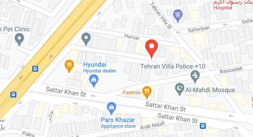
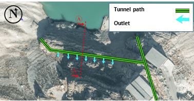 Schematic location of diversion tunnel 01 and its connection to Joint LP
S.A.S decided to conduct dye injections at levels under the water surface. Otherwise, all calculations of the outflow velocity would be unreliable because of neglecting the head pressure and velocity in the holes under the water surface. There are 4 leakage points along with the D-3 line which is surveyed by Terra Company.
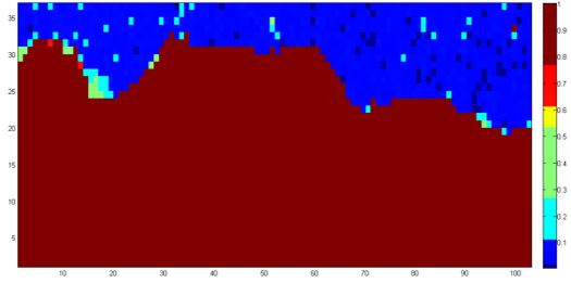 Velocity magnitude of flow in D-3 line (Terra Company) (m3/s)
During several site visits, S.A.S Company found out that there is a need for more attention to small leakage points, which could accumulatively produce a significant leakage flow rate. They also found out a loud voice, coming out from inside the mountain at outlet points and under the lateral facilities at the right abutment, Emamanak Valley and its upstream that neglected before as probable leakage points. After the last field monitoring, by using the obtained data of water surface elevation in each monitoring period, the changes in water elevation during total periods of monitoring investigated
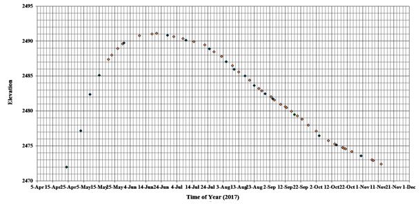 Changes of surface water elevation during monitoring periods
The investigations made by S.A.S revealed that:
- Two points are more sensitive: the first one is diversion tunnel 01 and the second one is upstream of Emamanak Valley.
- The tunnel has no lining and there are several long cracks and holes on the wall of this tunnel. Therefore, providing surface lining and grouting cement for the Tiz-Kuh structure without sealing lining will not so effective to solve the problem because this tunnel transfer water flow by cracks and hole into the surface water and this problem will be intensified under the hydrostatic pressure when the water level is high.
- The upstream site of the Emamanak valley is recommended to be covered by sealing lining. There is a need to investigate the stability and vulnerability of the dam by considering the fractures, determination of the capacity of the dam for current status which is able to store water up to 2531 m level.
- Investigation of changes in water level at Galugah and Haraz springs as outlet points should be carried out by tracing inspection and dye injections. Investigating the required strength to withstand the double hydraulic pressure at the level of 2531 m should be addressed in the future.
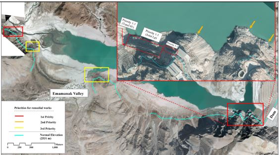 Prioritized treatment plan
")
")